glTF
This note is mainly a excerption of the official glTF Tutorial, combined with some other resources. Reading the official tutorial is recommended.
Introduction
glTF is an open interoperable 3D asset ‘transmission’ format that is compact, and efficient to process and render at runtime. glTF 2.0 is designed with following goals in mind:
- Compact file size
- Complete 3D scene representation
- Runtime independence
- Extensibility
A glTF asset is represented by:
- A JSON-formatted file (.gltf) containing a full scene description: node hierarchy, materials, cameras, as well as descriptor information for meshes, animations, and other constructs.
- Binary files (.bin) containing geometry, animation, and other buffer-based data.
- Image files (.jpg, .png) containing texture images.
Basic Concepts

Here's what a minimal glTF looks like:
Minimal glTF
{
  "scene": 0,                   // Default scene for this gltf
  "scenes" : [                  // Scense stored in this gltf
    {
      "nodes" : [ 0 ]           // Root nodes of each scene, accessed with indicies
    }
  ],
  "nodes" : [
    {
      "mesh" : 0                // Mesh refered by this node
    }
  ],
  "meshes" : [
    {
      "primitives" : [
        {
          "attributes" : {
            "POSITION" : 1
          },
          "indices" : 0
        }
      ]
    }
  ],
  "buffers" : [
    {
      "uri" : "data:application/octet-stream;base64,AAABAAIAAAAAAAAAAAAAAAAAAAAAAIA/AAAAAAAAAAAAAAAAAACAPwAAAAA=",
      "byteLength" : 44
    }
  ],
  "bufferViews" : [
    {
      "buffer" : 0,
      "byteOffset" : 0,
      "byteLength" : 6,
      "target" : 34963
    },
    {
      "buffer" : 0,
      "byteOffset" : 8,
      "byteLength" : 36,
      "target" : 34962
    }
  ],
  "accessors" : [
    {
      "bufferView" : 0,
      "byteOffset" : 0,
      "componentType" : 5123,
      "count" : 3,
      "type" : "SCALAR",
      "max" : [ 2 ],
      "min" : [ 0 ]
    },
    {
      "bufferView" : 1,
      "byteOffset" : 0,
      "componentType" : 5126,
      "count" : 3,
      "type" : "VEC3",
      "max" : [ 1.0, 1.0, 0.0 ],
      "min" : [ 0.0, 0.0, 0.0 ]
    }
  ],
  "asset" : {
    "version" : "2.0"
  }
}
Scenes
The entry point to the nodes and composition of a scene stored in the glTF. A glTF can contains multiple scenes, but one default scene must be provided. Each scene is composed of an array of indicies of nodes.
Node
Nodes that form the scene are stored in an array. Each node within the array can contain contain an array of indices of its children. This allows modeling a simple scene hierarchy.
A node may contain a local transform, either given as a column-major matrix array or with separate translation, rotation(given as a quaternion) and scale properties.
The local transform matrix is then computed as M = T R S where T, R and S are the matrices that are created from the translation, rotation and scale. Note that the computation sequence CAN NOT BE CHANGED.
The global transform of a node is given by the product of all local transforms on the path from the root to the respective node.
The translation, rotation and scale properties of a node may also be utilized by an animation that describes how one property changes over time. The attached node, either a 3D object or a camera, will move accordingly.
We now know that amount of transformation computation is massive, not to say local transform of a node can be modified for animation purpose, which affects the global transform and requires re-compute.
Alternatively, and as a potential performance improvement, an implementation could cache the global transforms, detect changes in the local transforms of ancestor nodes, and update the global transforms only when necessary.
Each node may use indices that point to the meshes and cameras arrays to refer to a mesh or a camera that is attached to the node.
Nodes are also used in vertex skinning: A node hierarchy can define the skeleton of an animated character. The node then refers to a mesh and to a skin. The skin contains further information about how the mesh is deformed based on the current skeleton pose
"nodes": [
  {
    "matrix": [
      1,0,0,0,
      0,1,0,0,
      0,0,1,0,
      5,6,7,1
    ]
  },
  {
    "translation": [ 0,0,0 ],
    "rotation": [ 0,0,0,1 ],
    "scale": [ 1,1,1 ]
  }
]
Meshes
The meshes may contain multiple mesh primitives, referring to the geometry data that is required for rendering the mesh. Mesh raw data is stored in the .bin file.
A mesh describes a geometric object that appears in the scene. It refers to accessor objects that are used for accessing the actual geometry data, and to materials that define the appearance of the object when it is rendered.
The mesh itself usually does not have any properties but only contains an array of mesh.primitive objects, where each describes an indexed geometry indicated by the indices property.
The mesh primitive contains an array of attributes. These are the attributes of the vertices of the mesh geometry, in this case, the POSITION attribute describes the positions of the vertices.
By default, it is assumed to describe a set of triangles, so that three consecutive indices are the indices of the vertices of one triangle.
Camera
The camera defines the view configuration for rendering the scene.
Accessor
The accessor is used as an abstract source of arbitrary data. It is used by the mesh, skin, and animation, and provides the geometry data, the skinning parameters and the time-dependent animation values. It refers to a bufferView, which is a part of a buffer that contains the actual raw binary data.
Material
The material contains the parameters that define the appearance of an object. It usually refers to texture objects that will be applied to the rendered geometry.
Texture
The texture is defined by a sampler and an image. The sampler defines how the texture image should be placed on the object.
Buffer
A buffer contains a URI that points to a file containing the raw, binary buffer data:
{
  "buffer01": {
    "byteLength": 12352,
    "type": "arraybuffer",
    "uri": "buffer01.bin"
  }
}
This binary data is just a raw block of memory that is read from the URI of the buffer, with no inherent meaning or structure. The Buffers, BufferViews, and Accessors section will show how this raw data is extended with information about data types and the data layout.
Buffer views
A bufferView describes a “chunk” or a “slice” of the whole, raw buffer data.
Accessors
An accessor object defines how the data of a bufferView has to be interpreted by providing information about the data types and the layout.
Image
An image may refer to an external image file, usually in PNG or JPG for efficient transfer due to their small size, that can be used as the texture of a rendered object.
As an alternative, the data may be embedded into the JSON, in binary format, by using a data URI.
Animation
The animation describes how transformations of certain nodes (e.g., rotation or translation) change over time. Animation raw data is stored in the .bin file.
Skin
The skin defines parameters that are required for vertex skinning, which allows the deformation of a mesh based on the pose of a virtual character. The values of these parameters are obtained from an accessor. Skin raw data is stored in the .bin file.
Train of Thoughts
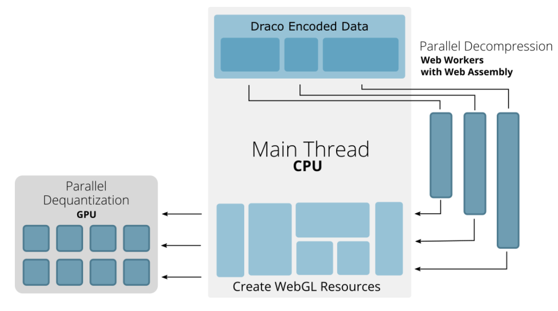
How draco decode works ?
Extension
KHR_draco_mesh_compression vs EXT_meshopt_compression
KHR_draco_mesh_compression
- Pros: Higher compression rate suitable for gltf that has large poly counts
- Cons: Requires decode and has a longer load time; requires downloading decoder and has large download size
EXT_meshopt_compression
- Pros: Relatively good compression rate and has a faster load time
- Cons: Lower compression rate for high poly count models compared to draco